
目录
Commonly used dynamic anchoring systems may encounter considerable challenges during their operations in unstable, weak, or fractured geological strata. Ground collapsing prior to drilling and boreholes clogging while casing is being pulled back may become serious obstacles to installing such systems efficiently. The Hollow Injection Bar system eliminates these challenges by combining drilling, grouting, and anchoring operations in one phase as an efficient base for constructing structures related to civil engineering, tunnelling, or slope stabilization purposes. The following step-by-step guide explains the key installation procedures, from site preparation and drilling to grouting and final anchoring, to help ensure a safe and efficient installation.
Pre-Installation Preparation for Hollow Injection Bar Installation
The installation of the Hollow Injection Bar will require proper site surveys, material selection, and equipment preparation. The operators should establish definite technical requirements before performing drilling work.
Geotechnical and Equipment Survey
Tolerance for the angle of the boreholes (usually +/- 0.5 degrees) and depth of drilling design. Select drilling machines having torque of 2,500 Nm to 6,000 Nm.
Staging of Components
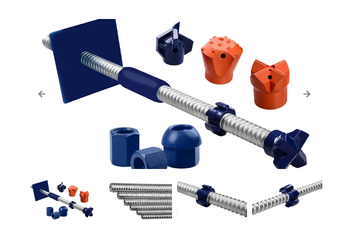
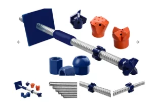
Examine all delivered materials manufactured by reliable companies, such as ONTON. Examine the quality of the sacrificial drill bit, couplers, bearing plates, hex nuts, and anchor bar body.
Grout Mix Design
Either neat cement slurry or polymer-modified grout. The ratio of water to cement should be between 0.40 and 0.50 to guarantee a compressive strength of 30 MPa after a 7-day curing process.
Table 1: Technical Properties and Purpose of Materials
- Steel Grade of Bar: Minimum yield strength = 460 MPa; Minimum tensile strength = 650 MPa. Purpose: Resistance to the stress resulting from dynamic drilling processes.
- Drill Bits Selection: Button bit in hard ground/Cross bit in soft or fractured ground. Purpose: Boring through the soil layers with transport of flushing media.
- Grout Pressures: Primary = 0.5 to 1.0 MPa; Secondary or Final = 2.0 to 4.0 MPa. Function: Filling of radial gaps and fissures in the surrounding.
Procedure for installing Hollow Injection Bar System
Hollow injection bar installation needs accurate alignment between the drilling rig and grout pump to create a composite grout-soil body.
Step 1: Rig Positioning and Bit Attachment
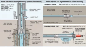
Position the drill mast accurately using survey coordinates. Screw the selected drill bit into the first lead bar part. Make sure the screw connections are tight to avoid any leakage of the flushing fluid.
Step 2: Simultaneous Drilling and Grouting
Start the slurry pump before rotation begins. Push the bar while pumping a high-pressure grout through the center of the system. The grout is discharged through radial holes of the drill bit, cleaning cuttings and filling fractures simultaneously. Keep the advance rate at 0.3 meters per minute to 0.8 meters per minute to guarantee full perimeter grouting.
Step 3: Couplers to Extend the Segment
As soon as the primary Hollow Injection Bar reaches the bottom of the hole, turn the bar and remove the thread of the connection. Screw in the high-strength coupler and insert the next bar. Torque (torque equals 150 to 200 Nm) the joint to prevent joint loosening and dynamic fatigue during the percussive drilling process. Do it until you get the required depth.
Step 4: Post-Grouting Pressure Stabilization
After you have reached your desired anchor depth, increase the pump pressure up to 2.5 to 3.5 MPa for 2 to 3 minutes. This pressure pulse causes the development of the enlarged bulb of grout in the anchoring zone. Thus, the increase in the bond strength is 20% to 35% compared to gravity grouting.
Step 5: Anchor Head Assembly and Tensioning
After the grout body achieves the initial set (approximately 24 to 48 hours), mount the bearing plate over the exposed thread end. Insert the spherical hex nut and torque it up to the required alignment. If there is a need to use active pretensioning according to design, then load using the hollow hydraulic jack after the grout attains 80% of its 28-day characteristic strength.
Field Troubleshooting and Best Practices for Hollow Injection Bar Deployments
Unexpected geologic conditions call for prompt changes in the process during drilling.
Grout Circulation Loss
Grout may leak away and be unable to return in situations of fractured limestone and gravel rocks with high porosity.
Solution:Reduce the water-to-cement ratio to 0.35 or add rapid-hardening admixtures (accelerators with 2- 3% of cement mass). Carry out drilling in short sections to stop leaks.
Rotation Stoppage and Threads Jamming
The resistance of the rock layer may cause a stoppage of rotation or threads jamming.
Solution: Remove water from the central bore with a pressure of 5-8 MPa to clear the clogged passage and rotate it slowly with grout.
Full Geological Adaptation and Quality Assurance
In addition to the basic installation procedure, safety and longevity of the Hollow Injection Bar structure depend on adaptation of the installation process according to different soil and rock classes. The key feature of the system of anchors is its adaptability in varying geologic conditions.
Response to Granular and Cohesive Soils
For loose sand and clay formations, collapse of the borehole wall poses the greatest risk. Existing technology involves the use of cumbersome casing tubes, which increases equipment transport costs and labor requirements. The continuous injection of slurry ensures that the cement slurry acts as a temporary liquid casing. With rotation of the drill bit, the mixture of the slurry and surrounding soil ensures a very dense soil-cement mixture, which significantly increases the Hollow Injection Bar’s friction.
Checklist for Quality Control and Field Testing
To comply with international engineering standards, contractors need to keep quality logs of all installed members:
- Drilling Logs: Penetration rate per minute, rotational torque, and feed pressure should be noted to identify any voids or hard granite layers.
- Grout Consumption Ratio: The volume of grout pumped needs to match the volume of the hole drilled. Ratios of 1.2 and 1.5 suggest proper filling of voids.
- Verification Pull-Out Tests: Conduct destructive and non-destructive pull-out tests on 3% to 5% of bars that have been inserted after 28 days of the curing process. Test loads should be applied at 120% to 150% of the design working load to test the efficiency of bond stress.
Conclusion
The Hollow Injection Bar provides a simple solution for geotechnical support in intricate construction conditions by integrating drilling, inserting, and grouting into one effective procedure. The employment of high-quality anchors provided by ONTON minimizes dangers in difficult operating conditions. The accurate maintenance of grout pressure, optimization of slurry mixture, and correct torque parameters of joints allow for the provision of longevity and durability of structures.
0